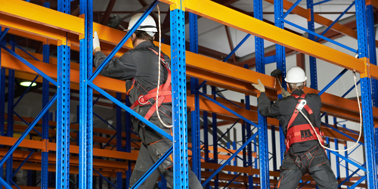
Making A Tight Beam-To-Column Connection

To ensure that a pallet rack beam does not separate from an upright rack column as a result of either an impact or seismic event, RMI’s ANSI MH16.1-2012: Specification for the Design, Testing and Utilization of Industrial Steel Storage Racks specifies how a steel storage rack manufacturer should calculate the number of engaged locking mechanisms (such as pins, bolts, or other devices that resist disengagement).
In general, the more pins or bolts used to connect a beam to a column (typically ranging from two to four), the tighter the connection. This yields higher load capacity, as well as greater resistance to both vertical and lateral (or horizontal) forces. In high seismic zones, for example, racking should be engineered to not only hold a pallet load securely, but also to withstand the side-to-side motion caused by an earthquake. This ensures the rack system can withstand lateral forces and minimizes the chance of collapse.
Specific to racking systems loaded by forklift, Section 5.4 in MH16.1-2012 covers beam-to-column connections, noting:
Except for movable-shelf racks, beams subject to machine loading shall have connection locking devices (or bolts) capable of resisting an upward force of 1,000 pounds (453.6 kilograms) per connection without failure or disengagement.
Section 2.6.4 provides guidelines for determining the maximum rotational capacity of a beam-to-column connection in a seismic zone.
Every storage rack manufacturer utilizes one or more unique beam-to-column connections. The assembly requirements for both the connection and its strength and stiffness result from the manufacturer’s testing. As detailed in section 2.4.1 of the ANSI MH16.1-2012: Specification, three different tests can be applied when determining the proper number of beam-to-column connections to create the strongest structure:
Cantilever Test (Section 9.4.1) – Conducted to determine the beam-to-column connection’s moment capacity. Set-up includes one column segment and one beam segment connected to each another with a load applied downwardly in the plane of the frame at the cantilever end of the beam segment.
Portal Test (Section 9.4.2) – Another test to determine the beam-to-column connection’s ability to resist force and its rotational rigidity. Specifically, this test is used to obtain a joint spring constant needed for semi-rigid frame analysis. It utilizes two column segments connected by a single beam in between—creating a portal frame. The load is applied both laterally in the plane and to the corner of the portal frame in the direction parallel to the beam segment.
Cyclic Test (Section 9.6) – Specifically designed and conducted to determine the beam-to-column connection’s earthquake force resistance, inelastic rotational capacity and rotational stiffness, as well as its energy-dissipation properties, this test subjects the connections to cyclic (repeated) loading conditions. The test set-up creates a double cantilever, with two beam segments connected to a single column, and applies the load to the end of the beams in an alternating fashion.
Based on the results of the tests, the rack manufacturer will include specific beam-to-column connection instructions on the installation’s Load Application and Rack Configuration drawing.
Want to learn more about beam-to-column connections? Section 5.4 of the ANSI MH16.1-2012: Specification includes more details.


