The Importance Of Uniform Load Placement To Cantilevered Storage Rack Safety
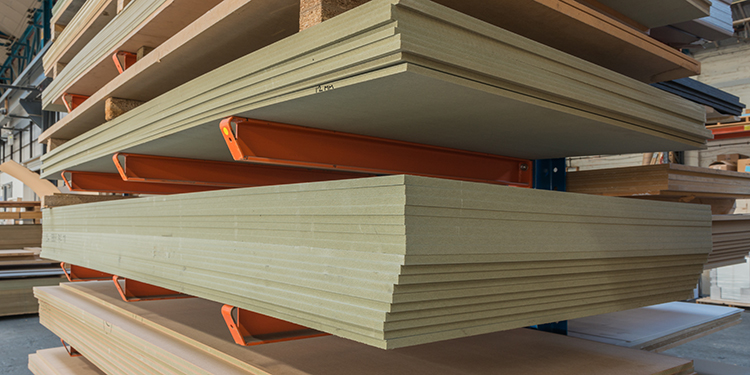
Designed and engineered to store very long loads — such as building materials including piping, lumber, or bar stock — cantilevered storage rack structures incorporate central, vertical columns from which horizontal arms project perpendicularly on one or both sides, with no vertical column connecting the arms on the aisle face. Loads are placed down-aisle (or parallel to the load access face of the rack) on two or more arms which have been designed to hold a specific, evenly distributed weight. To ensure the integrity of the storage system, it is critical that the load, for which the cantilevered rack structure has been designed, is placed on the arms in a uniform, symmetric manner.
For example, for a load that measures 180 inches and weighs 3,000 pounds, the racking might be designed with three arms spaced 60 inches apart and each arm supporting a 1,000-pound load. To prevent any of the arms or columns from becoming overloaded, the load must be placed such that there is 30 inches of overhang (half of the column center-to-center distance) off the ends of the two outermost arms. This ensures that the load is properly balanced — side to side — across the rack arms.
Uniform load distribution across the arms should always occur when placing a load into cantilevered storage rack, regardless of the number of arms (two, three, four or more) utilized to hold the stored items. If the load is positioned too far to one side or the other of the outermost arms, a disproportionate amount of stress will be placed upon the exterior arm(s) which could cause them to be overloaded.
To avoid such a situation, it is critical that forklift operators be trained to place the load symmetrically on the cantilevered rack arms. Further, they should store a load only within the section of cantilevered rack that has been designed specifically to hold it. That determination will be made by the professional rack engineer who designed the system based on a variety of details about the products to be stored, including sizes, dimensions, weights, and degree of rigidity or flexibility. For loads that are more flexible, more arms may be needed to support them, given these types of loads may cause undesirable side pressure on the arms.
If the racking has been designed to hold different loads in specific bays of the system, operators should be trained to recognize where individual products should be stored. Some operations use a color coding or alphanumeric labeling system to identify each load and its corresponding storage location within the cantilevered racking as a visual cue for forklift operators.
Sometimes an operation will need to store a new load type with dimensions, weight, or other characteristics outside the scope of the cantilevered rack’s original design. Before making any changes to the rack’s configuration, it is important to consult the system’s load application and rack configuration (LARC) drawings first. The LARC drawings will show the different arm configurations and load capacities that the system’s components can safely support.
If the rack system’s owner desires a configuration different than the options shown in the LARC drawings, the original rack manufacturer (preferably) or a qualified rack design engineer should be consulted to re-evaluate the capacity of the system and add new documentation to the package of LARC drawings. If significant modifications are made to the structure’s configuration such that load capacities change, load plaques should be updated accordingly.
Want to learn more about the safe design, manufacture, and installation of cantilevered rack systems? Download RMI’s ANSI MH16.3 Specification for the Design, Testing and Utilization of Industrial Steel Cantilevered Storage Racks.