The Importance Of Matching A Drive-In Rack Design To A Specific Forklift
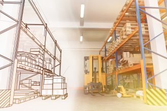
Ideal for storing multiple pallet loads of the same product, drive-in rack maximizes cubic storage space within a facility by eliminating multiple travel and access aisles. These structures are designed and engineered with upright frames, rails, and ties (but no horizontal beams except at the very top and across the back). Drive-in rack allows a forklift to enter from one side only to pick up or deliver pallets that rest on continuous rails. Because the forklift will be fully entering the structure — as deep as five to 10 pallet positions — one of the most critical aspects of drive-in rack design is the type and dimensional specifications of the forklift (or multiple forklifts) interfacing with the structure. Indeed, the majority of 10-deep drive-in racks are designed as two sets of 5-deep racks, installed back-to-back, so the vehicle doesn’t have to travel so far within the structure.
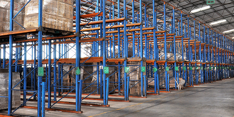
Loads are placed in a drive-in rack system in a specific order: back to front. To place the first load, a forklift must enter the drive-in rack with its mast (and load) fully elevated to the highest and furthest storage position to place the first load so as not to make contact with the structure. Not only does this make drive-in rack a last-in, first-out (LIFO) inventory system, it also means that the structure’s pallet position openings must be sized to match the overall width of the forklift. This ensures that the vehicle has enough clearance side-to-side when entering and exiting the structure so as to avoid contact with the columns and rails.
Counterbalanced forklifts — weighted at the rear of the truck to prevent forward tipping of the truck when lifting a load — are the optimal type of vehicle for loading and unloading drive-in rack. Conversely, straddle trucks or stackers with wide, fixed outriggers for load handling stability should not be used with drive-in rack. That’s because each bay within a drive-in rack is sized to support a given pallet dimension; anything significantly wider than the opening (like outriggers) will impact the rack columns and potentially cause the structure to fail. Some operations elect to use reach or deep-reach forklifts for loading and unloading drive-in rack; clearance accommodations for the additional fork length must be made to avoid collisions with the structure when entering and exiting from the access aisle.
In addition to the forklift’s width, other considerations in drive-in rack design include the height of the vehicle’s overhead operator cabin guard. Available clearance under the first elevated pallet rail position must be enough to permit the vehicle to fit beneath it and prevent the risk of impact. Further, the structure’s base plates — which anchor the drive-in rack’s upright columns to the floor — must be wide enough to ensure stability. That means the forklift’s wheels must be spaced to sit inside the base plates to avoid running over them.
Operations considering a drive-in rack installation should share these key forklift dimensions with the rack manufacturer at the outset of the design and engineering process to save time. Those with existing drive-in rack structures considering replacing or adding new forklifts to their fleet for use in the rack should pay careful attention to these rack dimensions when selecting a vehicle. The rack engineering drawings will not specify the dimensions or type of truck assumed but will only show the dimensions of the rack. It is the responsibility of the integrator to ensure that the truck and the rack are completely compatible.
Looking for answers to other industrial storage rack system safety questions? Visit RMI’s page of frequently asked questions (FAQs).