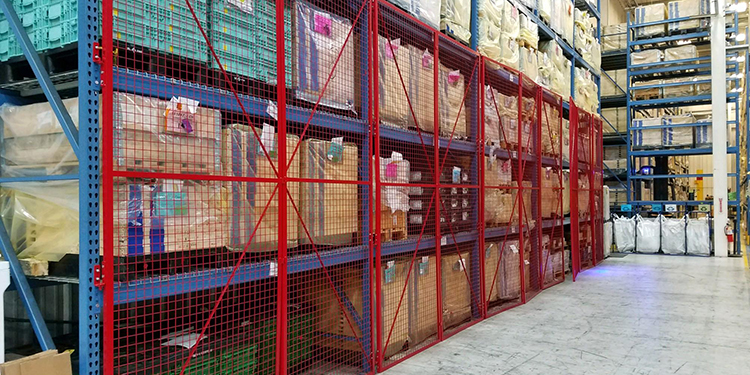
To ensure a safer, and, therefore, more productive operation, owners of industrial steel storage racking are responsible for posting rack load capacity plaques in conspicuous locations. They should also refer to the system manufacturer’s load application and rack configuration (LARC) drawings prior to making any rack configuration changes. Both documents convey important information about detailing the maximum safe storage capacity a given racking structure can hold without risking a collapse.
Required Information on Load Capacity Plaques
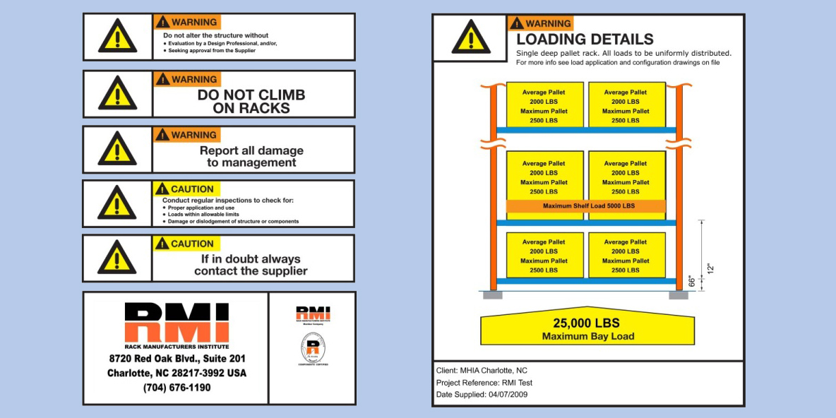
Posted in areas where personnel — including forklift operators — can see them, load plaques should include key information. According to RMI’s ANSI MH16.1: Specification for the Design, Testing and Utilization of Industrial Steel Storage Racks, this includes:
- The maximum permissible unit load (the combined weight of product and its storage container or pallet) and/or maximum uniformly distributed load per level.
- The average unit load (calculated as the maximum total weight of product expected on all beam levels in any row, divided by the number of beam levels in that row), if applicable.
- The maximum total load per bay.
- Indication of storage levels that support stacking of multiple unit loads.
The information is a concise, visual reminder of the maximum distributed pallet load capacity each storage position can hold. Following these details prevents forklift operators from overloading the rack. The rack manufacturer often provides load capacity plaques upon installation and commissioning of the system. Best practice is to place a plaque at every point of system entry and/or every different rack configuration. Although not required by RMI/ANSI MH16.1, many load capacity plaques also contain other details. This information may be about the manufacturer, the system’s date of manufacture or installation, safety warnings, and other structure-specific details.
Consult LARC Drawings Before Reconfiguring Rack
Should a facility’s storage needs change (for example, pallet loads become shorter or taller), and management wishes to adjust the beam elevations to accommodate other load heights, they should consult the LARC drawings first.
Many rack integrators or manufacturers will work with a customer to determine both current and potential storage needs prior to designing the system. The LARC drawings will show the different beam configurations and load capacities that the system’s components can safely support. Any modifications to the racking’s structure must use the same components and precisely match the drawing specifications indicated on the LARC drawings.
If the rack system’s owner desires a configuration different than the options shown in the LARC drawings, they should consult the original rack manufacturer (preferably) or a qualified rack design engineer first. They will re-evaluate the capacity of the system and add new documentation to the package of LARC drawings. Further, if significant modifications are made to the structure’s configuration such that load capacities change, load plaques should be updated accordingly.
Additionally, should a rack structure be damaged and subsequently repaired (preferably by the original rack manufacturer), LARC drawings showing the placement of the engineered repair kit(s) used — as well as details about the size of the replacement columns, position of splices, frame bracing, anchorage, and baseplate modifications — should be created and added to the LARC documents.
Learn More About Safe Rack Design and Use
Want more information about load capacity plaques and LARC drawings? The RMI/ANSI MH16.1: Specification is available for purchase.